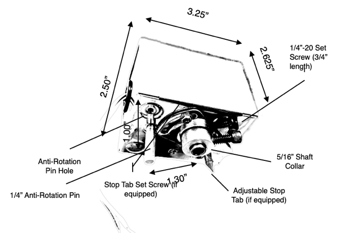
The RetroZone™ 2 wire spring return damper motors are designed as drop in replacements for Honeywell’s M847D series motors on popular ZD and ARD dampers, including M847D1004, M847D1012, and many other damper actuators that use the same footprint.
Please review these specifications and dimensions carefully to ensure correct fit and function for your application.
SPECIFICATIONS:
- Voltage: 24vac ± 10%, 60 Hz, 0.36A
- Torque Rating: Power open 32 in. oz./spring close 32 in. oz. - torque is consistently delivered throughout the full 90º rotational operating range to open and close the damper, irrespective of whether the actuator is operating in Power Advance Mode (energized) or Spring Return Mode (de-energized)
- Speed Stroke: Motor driven 30 sec./spring return 6 sec.
- Rotating Angle: 93.5º
- Noise Level: Very quiet operation, typically ≦ 40dB at 3’
- Reliability: Statistical life reliability exceeds 120,000 cycles at 90% reliability and 100% confidence with no decay in delivery torque over the life of the actuator
INSTALLATION:
CAUTION - Disconnect power supply before connecting motor wiring to prevent electrical shock or equipment damage.
- Using a 1/8” hex wrench loosen the motor coupling from the blade shaft and remove the existing motor assembly.
- Ensure that the damper blades are in the correct installation position:
- Damper attached to zone control system is normally open - make sure damper is in the open position.
- Damper attached to thermostat or switch is normally closed - make sure damper is in the closed position.
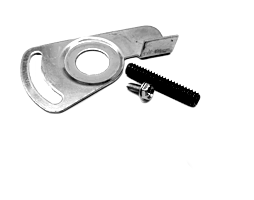
Adjustable Stop Tab with Set Screw and installation Screw (if equipped)
Replacement Damper Motor Actuator for HONEYWELL ARD ZD M847D 2 Wire Spring Return Motor RZ3-1M and RZ3-1MBStop Installation Trouble Shooting
✧Damper - Open or Closed:
If the damper you are working on is attached to a zone control system, then the damper must be in the open position when the motor is tightened or attached to the damper shaft. If the damper you are working on is connected to a thermostat or switch, then the damper must be in the closed position when the motor is tightened or attached to the damper shaft. It can be difficult to determine the open blade position of the damper in the field, since it is often not visible. On a damper connected directly to a zone control system, the damper will be typically normally open, power to close. On a damper connected directly to a thermostat or switch, normally closed, power to open. This step requires the damper motor to not be powered.
Normally Open Dampers: When looking at the back of the mounted motor on the damper, the blade is turned counter clockwise to close airflow, and under spring return power the blade rotates clockwise. (If your damper is normally closed, see 4 below.)
1. Turn the damper blade counter clockwise till the internal blade seals (most modern dampers will have blade seals) stop the blade. Then carefully rotate the blade 90 degrees clockwise. This should be the fully open position of the damper. Now tighten the allen screw of the motor to the damper shaft.
2. Testing: Next tape a square of toilet tissue to a grill or register where airflow can be observed. Set thermostat serving that zone to Fan:ON. Observe airflow. Then set Fan back to AUTO. Go to another zone and set the Fan:ON. This should power the subject damper motor to close of airflow: verify your new motor is getting power with the LED light supplied with motor, or a voltage meter.
Normally Closed Dampers: You may encounter a “normally closed” damper (typically a damper connected directly to a thermostat or a switch, that is closed with no power applied, and powered to open - directly opposite of a zone control damper). In this case the mounting instructions above are reversed. Rotate the blade clockwise till stopped, then tighten the de-energized motor to the shaft; the blade when energized with then travel counter clockwise till open.
Note that other methods of determining blade position exist if you are having issues. It can often be easy to drill a small hole in the damper to observe blade position, remove a piece of flex duct, or in some other manner actually be able to see blade position. If you have not removed your old motor, you can try marking the shaft with a Sharpie, but the issue here is that your old motor may not fail in the fully open position due to gear train issues.
✧Installation Trouble Shooting:
Failure to move upon installation is typically the result of these field issues:
A. Zone Control Systems - Incorrect Expectation: Users often expect all dampers to power close when wired to a zone panel, and then open when that zone’s thermostat calls, but this is incorrect. When an HVAC system is at rest, with no thermostats calling, all dampers will be open with no power. THE ONLY TIME A MOTOR RECEIVES POWER TO CLOSE is when a thermostat for SOME OTHER zone calls for heat or cool. Zones that DO NOT NEED air only then power the motors to close a damper.
B. Failure to Supply Power to the Motor: Related to “A” above, due to problems with zone panels, bad relays, bad thermostats, or some other issue, motor never receives power. It is best to use a voltage meter to check for 24vac. In the absence of a voltage meter, it is acceptable to take the motor only and touch the two wires directly to the 24vac transformer inputs on zone board, or to the leads of another motor known to be working.
C. Jammed or Broken Damper: Make sure before installing the motor, that the damper itself rotates or moves freely.
To summarize operation of the 24vac RZ3-1 motor: looking at the back of the motor mounted on the damper, when powered the blade will move counter clockwise. When not powered, and being reversed by spring power, the blade will move clockwise. This is exactly the same operation as Honeywell M847D and similar motors - this motor is not turning “the wrong direction”.
But, these same directions of travel can be used for either a normally open or a normally closed damper, depending on how the damper was configured when installed. For instance, many dampers can be changed, in the field, from normally open to normally closed, by simply mounting the motor on the opposite side of a round damper.


